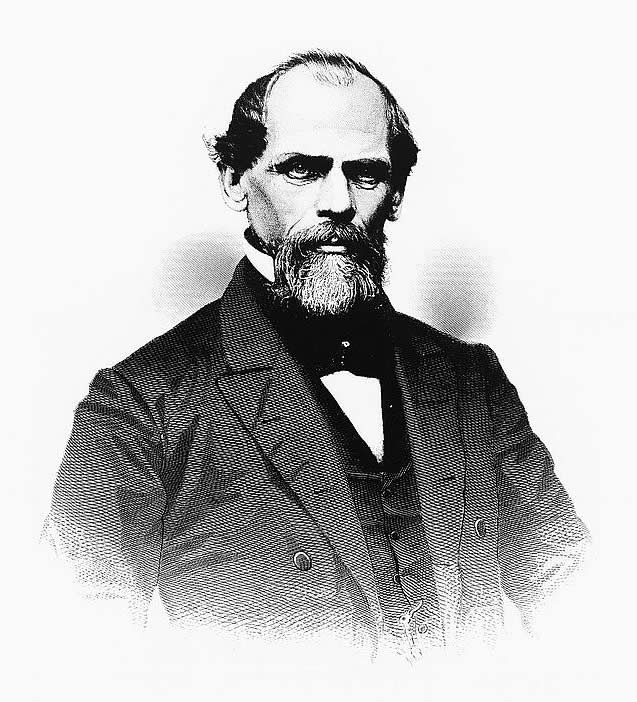
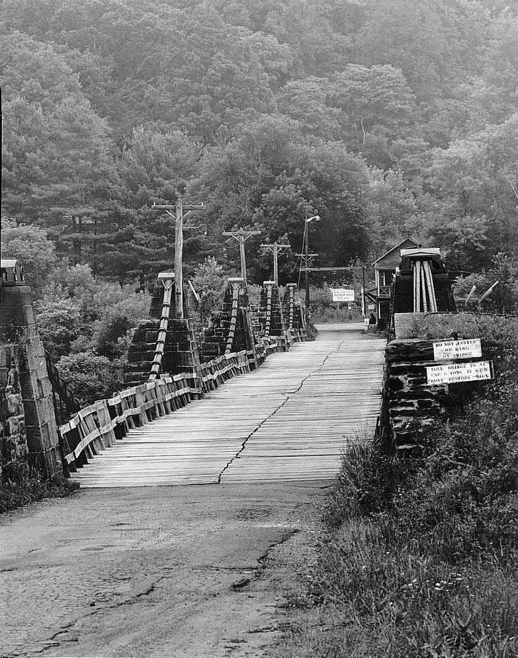
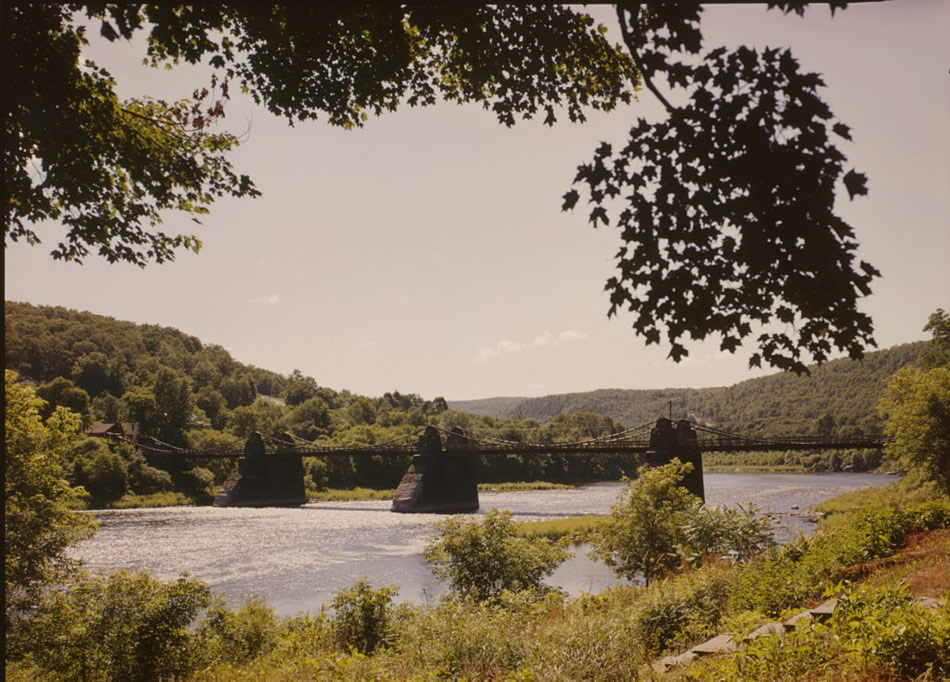
"The sight of a canalboat crossing a river was hardly remarkable in 1849 when, on April 26, a local crowd and engineers from all over the country gathered on the banks of the Delaware River in upper Pennsylvania. The boat in view was an ordinary barge. What was curious was how it got from shore to shore—floating inside a wooden flume suspended thirty feet above the water from two iron cables, which dipped across the river over stone piers." — Emma Cobb writing about Roebling's Delaware Aqueduct for American Heritage Magazine
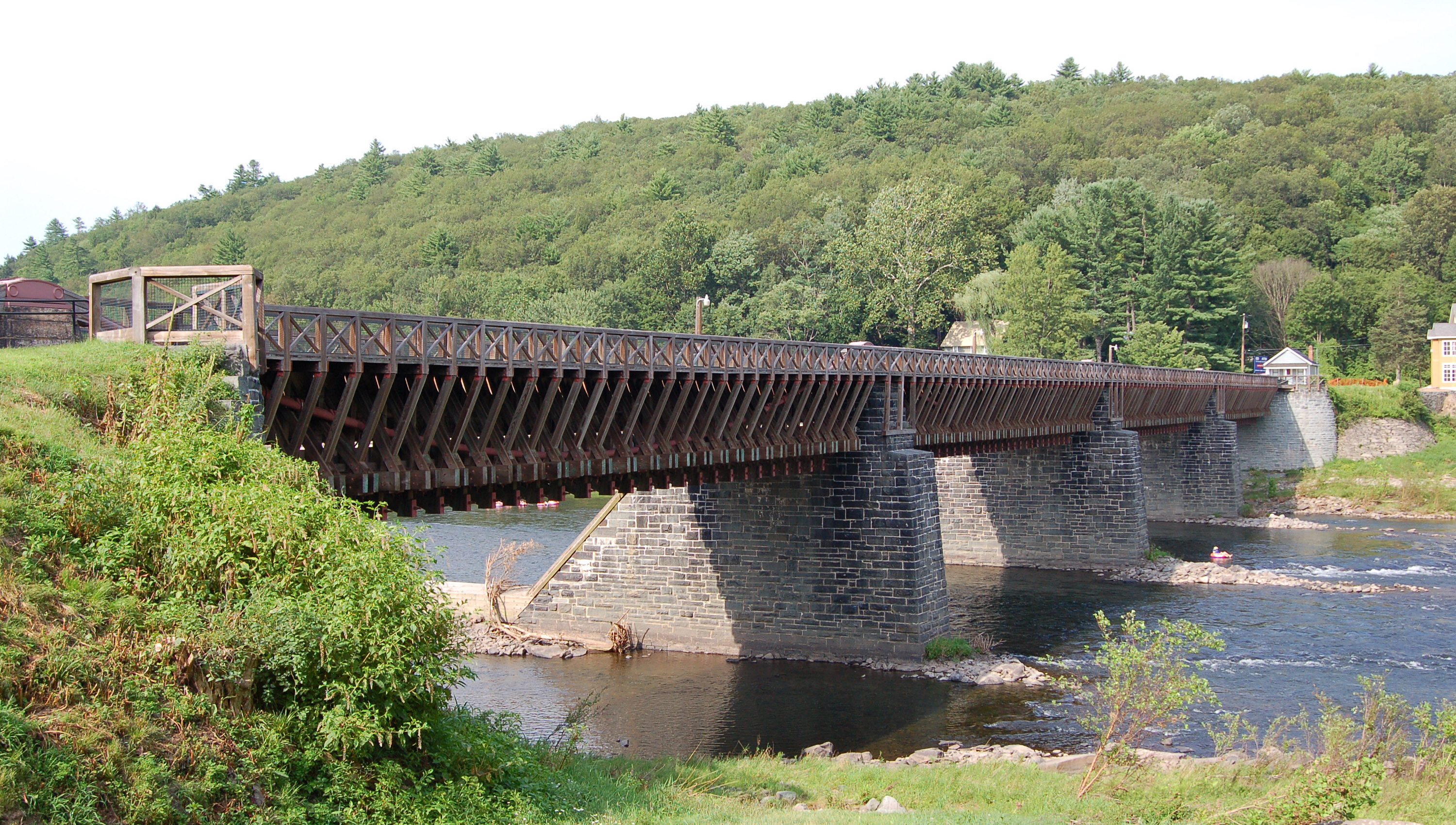
Even in 1849, aqueducts as Cobb described were nothing new. Loosely defined as a channel constructed to convey water, aqueducts have been around for thousands of years. However, what makes John Roebling’s Delaware Aqueduct special is not the action it performed – working as a massive aqueduct capable of carrying 2000 tons of water and boats laden with coal across the Delaware River as part of the Delaware & Hudson Canal. What makes it unique is how it performed its task: through a revolutionary suspension design incorporating iron-wire cables.
These iron cables are what set Roebling’s design apart. During the time when the Delaware Aqueduct was built, suspension bridges, or bridges in which the deck (load-bearing surface) is suspended below support cables, commonly used open link chains. Roebling’s use of wire rope, an attribute now inseparable from major suspension bridges, revolutionized the bridge industry and has helped the Delaware Aqueduct stand the test of time, making it the oldest suspension bridge in the United States.
A symbolic structure, the original use of the aqueduct as part of the Delaware & Hudson Canal strongly reflects the history of the time and place in which it was constructed. Since then, it has been modified many times, matching the changing face of transportation and evolution of northeastern Pennsylvania.
The Rise of the Delaware & Hudson
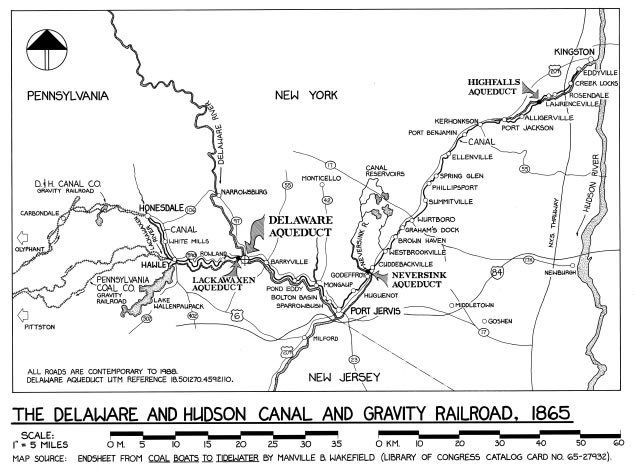
Around the turn of the 19th century, approximately 50 years before the construction of Roebling’s Delaware Aqueduct, the anthracite coal industry was still in its infancy; only since 1790 had anthracite been used as a fuel source in iron furnaces. It was not until 1808 that it would first be used to heat private residences; however, with this newfound use, the mining of anthracite coal exploded and people quickly began looking for ways to efficiently transport the material from the coalfields of northeastern Pennsylvania to huge potential markets in New York City.
With steam-powered railways not yet constructed in the United States and trucks still almost a century away, the only practical method for transporting the millions of tons of coal such long distances was via waterways. Unfortunately, most waterways in the interior of Pennsylvania were treacherous and difficult to navigate. This fact led to the construction of the Delaware and Hudson Canal, which opened in 1828 and provided a safe and effective route.
Though generally deemed successful, by the mid 1840’s certain major problems still existed in the canal. As D. B. Steinman points out in his book, The Builders of the Bridge, one such problem was the difficulty in crossing the Delaware River. “There was a bottleneck…at points where the canal and river crossed and their traffic mixed. At the Mouth of the Lackawaxen, the Delaware River was crowded with floating craft. At the same time that the anthracite-laden canalboats were attempting to move across the river, the lumbermen of the upper Delaware were running hundreds of pine and hemlock rafts down the stream.…”
As a response, owners looked for a better way to make the crossing and eventually requested proposals for an aqueduct that could carry their barges cleanly across the river. Most of the responses they received called for standard trusses; however, one design stood out. This was the design of a relatively new engineer by the name of John A. Roebling. His proposal recommended the use of a radical new technology – wire rope suspension bridges.
Why Wire?
Wire rope suspension bridges, which supported their loads via massive iron cables, offered an efficient, cost-effective solution capable of supporting heavier loads over longer spans. Roebling’s design in specific presented three major advantages over the truss bridges of his competitors: it allowed the river to be crossed in fewer spans, it increased the clearance between the bridge and the water’s surface, and it was much cheaper.
Fewer Spans Had Many Fans
First off, due to his suspension design, Roebling’s bridge required just four spans (one of 142 feet and three of 131 feet) in order to cross the Delaware. This meant constructing three piers in the river, compared to the four or five required by standard truss designs of the time. The first benefit of this had to do with ease of construction: building the piers along the riverbed was one of the most difficult and cumbersome aspects of raising a bridge, so fewer piers meant easier and speedier completion. Furthermore, eliminating piers also limited the material used in the bridge, keeping the price down. Finally, since Roebling’s design only contacted the river in three places rather than four or five, his structure offered much less impedance to floodwater, ice, and logging rafts, which resulted in less damage and fewer repairs.
The Desire to Be Higher
Another benefit of the suspension design was that it increased the clearance between the bottom of the bridge and the river below to around 30 feet. This, like the reduced number of piers, led to decreased sensitivity to flooding, ice flow, and timber rafts.
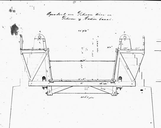
Higher clearance is inherent to suspension bridges. Most truss bridges are designed so the majority of their supporting structure is built below their load-bearing surface. On the other hand, the cables in a suspension bridge bear the structure’s entire load from above. This results in limited (if any) supporting structure below the load, which in the case of the aqueduct is water.
Roebling designed the bridge so that simple beams running the width of the structure and between the two cables supported the trough of the canal from underneath. Looking at one of Roebling’s drawings (pictured below) shows that this support beam is essentially the only part of the structure below the water in the trough (central hollow).
The two triangular shapes seen protruding below this beam are not actually used for support, but instead to help stiffen the bridge. Roebling was one of the first proponents of stiffening suspension bridges and he commonly incorporated stiffening trusses such as these into his work. At the time, many leading engineers disagreed with this extra support. However, disasters such as the collapse of the Tacoma Narrows Bridge in 1940 have since led to the acceptance of Roebling’s design.
Getting More for Their Money
The final and perhaps most important benefit of Roebling’s design was its cheap price tag. In suspension bridges, the majority of the weight of the bridge and its contents are supported by the cables, which transfer this weight to the towers on which they rest and to the ground where they are anchored. This means that the remainder of the bridge has little weight to bear and is mainly for stability and for transferring weight to the cables. This lack of structure compared to traditional truss bridges makes suspension bridges much cheaper, especially across long spans.
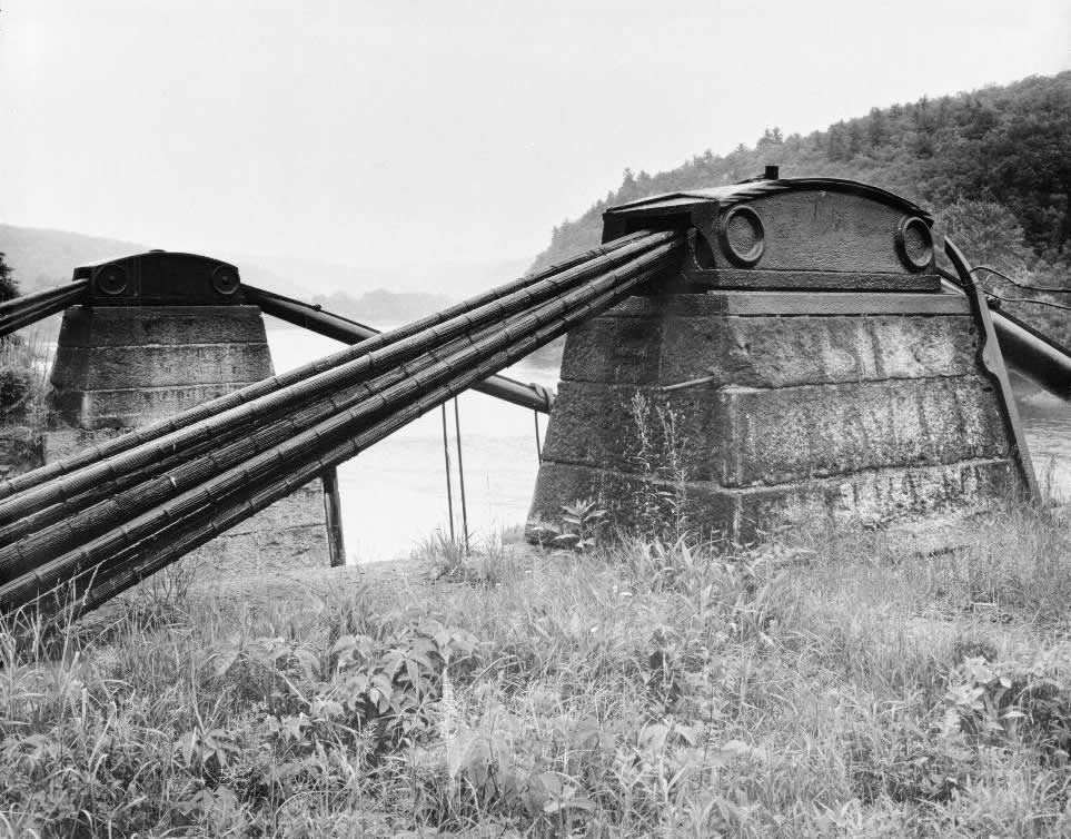
In addition, Roebling designed the Delaware Aqueduct in an ingenious way that further reduced the material (and therefore price) of the supporting structure. This was achieved by first moving the cables in from the outside of the structure to the edge of the trough and inside the towpath (as seen in the above sketch). This meant that the load being placed on the supporting beams by the water was much closer to the cables that supported these beams. Because of this decreased distance much smaller beams could be used. This effect is similar to how it is easier to hold a weight close to your body rather than at arm’s length. By bringing the weight closer to the supporting structure (you or the cables), it can be held with less resistance (smaller beams).
Even though Roebling designed the aqueduct to be self-supporting (the cables were only needed to support the water in the channel) and added stiffening trusses underneath, the cost of the structure was still much lower than a traditional truss bridge. Indeed, the final cost to the Delaware & Hudson Canal Company was a mere $41,750, of which $8,600 was Roebling’s profit.
Then Began the Dirty Work
With Roebling’s new design accepted on January 6, 1847, construction started almost immediately in March of the same year. Crews worked tirelessly and all cement work and masonry was completed by late summer to early fall. With the foundation and piers complete, Roebling began creating the structure’s ironwork.
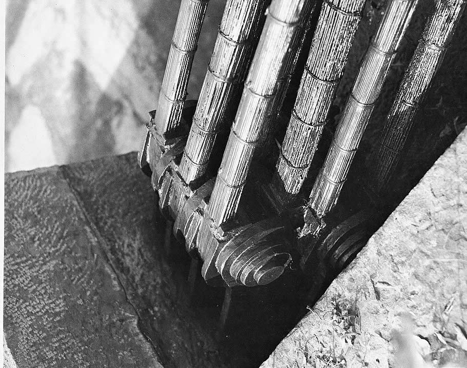
Roebling was renowned for the incredible care and oversight he put into the production of the ironwork for his bridges. As Sandra Speers, chief of planning and support services for the National Park Service, notes in an article in the Northeast Journal in 1987, “The more we got into it, the more we saw the actual thought and detail. There are so many minutiae of detail, like the wrought-iron metal work that was all hand crafted for each section. There are very elegantly graduated bars that are larger the higher they were placed, to carry a greater part of the load.”
Roebling put similar care into the iron wire rope he was known for pioneering in suspension bridges. He began producing this rope in 1841 in Saxonburg, Pennsylvania, years before he would design his first major bridge (the Allegheny Aqueduct in 1844). He originally sold this rope to railroad companies to replace the nine-inch circumference hemp ropes that were used to move railroad cars up and down the inclines. When he began designing bridges in 1844, he used this iron wire to replace the open-link chains in current suspension bridges. Iron wire became a trademark of sorts for Roebling and he incorporated it into all of his major bridges. Eventually the remainder of the industry would follow suit and metal wire would dominate suspension bridges ever since.
In the case of the Delaware Aqueduct, two 8½-inch cables were used, each composed of 2150 individual iron wires. The cables were spun in place with a piece of machinery invented by Roebling. When completed, the cables were capable of supporting stresses upwards of 90,000 pounds per square inch, for a combined total of around 3,870 tons. Needing only endure a stress of 770 tons as part of the fully loaded aqueduct, the cables were more than adequate.
With the completion of the cables and supporting structure in the winter of 1848, the Delaware Aqueduct and its companion the Lackawaxen Aqueduct (also designed by Roebling) opened in time for the 1849 canal season. Together it was estimated that they eliminated a full day from the travel time of the canal. Furthermore, in the first year alone, the structures allowed crossing of the Delaware River for nine days that would have previously have been impassible with the rope ferry system. This helped the canal to lower costs and provide quicker transportation, maintaining competition with up-and-coming railway systems.
The Dark Ages
The Delaware Aqueduct was used in Delaware & Hudson Canal for almost 50 years and throughout that time saved the company thousands of dollars and hours. However, in 1898, due to growing competition from the rails, the canal was forced to shut down, marking the beginning of a 80-year period of neglect.
Mirroring the changing times and the evolution of transportation, the Delaware Aqueduct was purchased in 1901 and converted to a vehicular crossing. The towpaths were sawn off and the now-dry aqueduct was used by its new owner to cart lumber across the river in addition to serving as a toll bridge to other travelers.
In 1933 a fire damaged large portions of the bridge, resulting in the woodwork being torn out. The deck was rebuilt, but the sides and towpaths were left off. From here, the bridge changed hands a number of times, with owners squeaking out a small profit by using it as a toll bridge. Finally, in 1977 a truck fell through the deck, threatening to close the structure for good.
Fortunately, the National Park Service (NPS) stepped in and bought the structure in 1980. Sadly, by this point the bridge was in shambles. That year Henry Magaziner, a regional historical architect for the NPS, noted, “All I had to do was hop up and down on one end and I could see a ripple running all the way from Pennsylvania to New York.”
Saved by the NPS
The restoration of the Delaware Aqueduct from its damaged state was of the utmost importance to the National Park Service. The bridge was already deemed to be of great historical significance, and had been named a National Historic Landmark in 1968 as well as a National Civil Engineering Landmark and American Society of Civil Engineering landmark soon after. Most importantly, it was the oldest standing wire suspension bridge in the United States.
Unfortunately, the original function of the aqueduct, holding large static loads of water (barges that moved across displaced their own weight in water and did not constitute a moving load) did not match well with the light, dynamic loads the bridge was being subject to as a vehicular crossing. Without the large water load, there was not enough static weight pulling down on the cables; the cables were free to slide around as cars and trucks crossed the bridge, causing damage.
The NPS eventually decided on a plan that would both preserve the historical significance of the bridge as well as stabilize the structure and protect it from damage. In this plan, which is now complete, the towpaths and walls of the aqueduct were rebuilt to original specifications using lumber, and a concrete roadbed running the length of the span replaced the weight of the water.
The Times, They Are A-Changin’
As the oldest remaining wire rope suspension bridge, Roebling’s Delaware Aqueduct represents a series of ideas that changed the construction of bridges even today. Revolutionary in its day, Roebling’s use of wire rope instead of chains, along with his emphasis on the importance of rigidity in suspension structures, changed the way people thought about bridges. One of the most highly regarded bridges in America reflects both the changes in bridge building methods and the importance of Roebling and his family: the iconic Brooklyn Bridge, built using techniques pioneered at the Delaware Aqueduct. From its original use a part of a canal carrying coal to its modern use as a toll bridge, the aqueduct serves not only as a symbol of the technological revolution of suspension bridges but also as symbol of shifting transportation and the changing times of northeastern Pennsylvania.
Sources:
- “1848 Delaware Aqueduct (Roebling Aqueduct).” www.Bridgemeister.com. Bridgemeister, 12 Mar. 2010. <http://www.bridgemeister.com/bridge.php?bid=30>.
- Buonopane, Stephen G. “The Technical Writings of John A. Roebling and his Contributions to Suspension Bridge Design.” ASCE. (2006): n. pag. 26 Feb 2010.
- Chang, Fu-Kuei, and Edward Cohen. “Rebuilding Roebling Delaware Aqueduct Bridge.” Journal of Structural Engineering 115.6 (1989): 1325-1341. “Death of Mr. John A. Roebling.” Boston Daily Advertiser. 24 July, 1869: 114.
- “Cobb, Emma. “Roebling’s Bridge of Water.” American Heritage. Summer 1986. 3 Mar. 2010. <http://www.americanheritage.com/articles/magazine/it/1986/1/1986_1_8_pri....
- Delaware Aqueduct Bridge.” en.structurae.de. Nicolas Janberg’s Structurae, 2010. 12 March 2009. <http://en.structurae.de/structures/data/index.cfm?ID=s0000260>.
- “Delaware & Hudson Canal.” nps.gov. U.S. National Park Service, 31 July 2006. 9 March 2010. <http://www.nps.gov/upde/historyculture/dhcanal.htm>.
- “Delaware & Hudson Canal, Delaware Aqueduct, Spanning Delaware River, Lackawaxen, Pike County, PA.” Historic American Engineering Record. Library of Congress. 9 March 2010. <http://lcweb2.loc.gov/cgi-bin/query/r?pp/PPALL:@field(NUMBER+@(pa1234))>.
- “John Augustus Roebling.” Encyclopædia Britannica. Encyclopædia Britannica Online, 2010. 9 Mar. 2010. <http://www.britannica.com/EBchecked/topic/506711/John-Augustus-Roebling>.
- “John Roebling.” nps.gov. U.S. National Park Service, 17 January 2008. 9 Mar. 2010. <http://www.nps.gov/upde/historyculture/john-roebling.htm>.
- Kranakis, Eda. Constructing A Bridge. Baskerville: Wellington Graphics, 1997.
- Lienhard, John H. “Roebling’s Other Bridge.” uh.edu. University of Houston’s College of Engineering, 1998. 12 March 2009. <http://www.uh.edu/engines/epi316.htm>.
- Magaziner, Henry J. “The Rebirth of an Engineering Landmark.” APT Bulletin 18.4 (1986): 52-64.
- McKay, John. Our Town: The History of Lackawaxen. Lackawaxen Township, 2010. 9 Mar. 2010. <http://www.lackawaxen.org/town.htm>.
- Rhodes, James W. “Credits.” Letter. APT Bulletin. 19.3 (1987): 2.
- “Roebling Revival On the Delaware.” New York Times (1923-Current file). 3 May 1987: 50.
- “Roebling’s Delaware Aqueduct.” AllExperts.com. AllExperts, 2010. 9 Mar. 2010. <http://www.britannica.com/EBchecked/topic/506711/John-Augustus-Roebling>.
- “Roebling’s Delaware Aqueduct.” nps.gov. U.S. National Park Service, 30 July 2006. 28 Feb 2010. <http://www.nps.gov/upde/historyculture/roeblingbridge.htm>.
- Rose, Andrew T. “John Roebling’s Development and Use of Wire Rope in Western Pennsylvania.” ASCE. (2006): n. pag. 26 Feb 2010.
- Sayenga, Donald. Ellet and Roebling. York, PA: The American Canal and Transportation Center, 1983.
- Steinman, D. B. The Builders of the Bridge. New York: Harcourt, Brace, and Company, 1945.
- United States Dept. of the Interior. National Park Service. Comprehensive Interpretive Plan: Upper Delaware Scenic and Recreational River. Washington: GPO, 1999.
- Unrau, Harlan D. Historic Structure Report Historic Data Section: The Delaware Aqueduct. Denver: Denver Service Center, 1983.
- Vogel, Robert M. ROEBLING’S DELAWARE & HUDSON CANAL AQUEDUCTS. Washington DC: Smithsonian Institution Press, 1971.

